


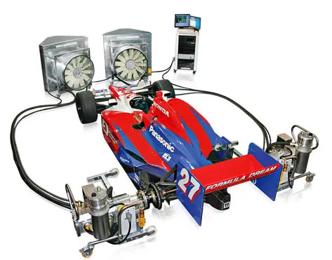
Chassis Dyno – which is best? (Copyright Torque Developments International)
Torque Developments International’s Technical Director – Sam Borgman offers this full and frank overview of chassis dyno hsystems.
As a car enthusiast you will undoubtedly hear the term “dyno” thrown around a great deal, with all kinds of people talking about power results measured on a dyno, engines that have been tuned on a dyno perhaps fault diagnosis which has been carried out on a dyno or even after market performance parts claiming to offer dyno proven power gains. The term Dyno is short for the word Dynamometer and a dynamometer is briefly defined as a machine which is used to measure torque and rotational speed, from which power can be calculated. Despite all of the publicity, exposure and the apparent importance of the dynamometer system to the car enthusiast I’ve found that during my time in the industry very few car enthusiasts I’ve met would say that they truly understand the whole subject of dyno’s and testing, and perhaps more worryingly they are completely unaware that there are good types of dyno systems which really are worthwhile seeking out and that there are types of dyno system which should probably be avoided or at least used only as a last resort. In the world of Dynamometers there are two major types, the engine dyno and the chassis dyno. The engine dyno is essentially a test bed on which to run an engine away from a car chassis and at the same time take measurements of the output. These systems are primarily used by tier-1 vehicle manufacturers or research companies working specifically on engine development they offer superior access to the engine for easy swapping of parts and they are directly coupled to the engine so measurement accuracy is potentially good, but they have downsides too. In order to use an engine dyno system the engine must first be removed from the cars chassis so for use by us in the aftermarket the engine dyno can prove undesirable for these main reasons. • High labour cost involved in removing and re-installing a car’s engine • Testing of the engine only, meaning that the performance of the actual power train as a whole remains an unknown. • The engine will ultimately be tested in a working environment which can often be very different to that of its eventual workplace inside the cars chassis and this can give rise to significant disparities between the engine dyno results and the engines real world performance. To better focus the scope of this article I’m going to concentrate on the type of dyno that you are much more likely to encounter, the chassis dyno, so from this point on when I use the term dyno I’ll be referring to a machine that is designed to test a complete engine, drive line and chassis combination. I’ll explain what ideally we need from a good dyno system, I’ll also try to give you a description of the common main types of dyno systems explaining briefly how they work and most importantly how the design of a system might affect your choice as to whether to use one type or perhaps another.
What do we need from a good dyno system? • It must have a sturdy and reliable physical interface with the chassis in order for the car chassis to transmit torque to the machine accurately and repeatabley. • It must have a direct method of torque measurement, the fewer links in the measurement chain the better. • The Torque measurement system must to able to be re-calibrated and tested with dead weights if necessary to ensure measurement reliability. • The dyno must be able to control the rotational speed on the chassis output extremely quickly and accurately in order to control the engine speed accurately during a test to ensure test repeatability. • It must have accurate rotational speed measurement. • In order for the results to be interpreted meaningfully the data gathering hardware and software on the dyno should be capable of monitoring real time atmospheric data, for instance both the ambient and engines intake air temperatures, the ambient relative humidity and the atmospheric pressure of the test environment. • A good dyno should be able to record and log other data streams taken from the car at the same time as the torque output and rotational speed information in order to make it useful as a tuning and diagnostic tool. Inertia Dyno’s
Intertia Dyno
Inertia dyno.JPG (104.96 KiB) Viewed 1682 times
Eddy current brake dyno example
Eddy current brake dyno example.JPG (48.3 KiB) Viewed 1701 times
These systems again either use two relatively small diameter rollers or a larger single hollow roller (which offer very little inertia) in order to transmit the output from the vehicle to the machine, the rollers themselves are normally directly coupled to an Eddie current retarder, which is essentially a large electrical disc brake which relies on electromagnetic forces rather than friction to create a braking resistance. These dyno’s are far more flexible than the straight un-braked inertia dyno’s because the Eddy current retarders can be computer controlled in order to give accurate and reasonably fast reacting rotational speed control by varying the resistance of the rollers. If understood and used correctly by a dyno operator this closed loop speed control feature removes the inherent inaccuracies caused by variable ramp rates you get during testing with inertia dyno’s. Good chassis speed control also allows the dyno operator enough control over the engine speed to be able to slowly and carefully navigate all of the possible speed and load conditions an engine might see in normal operation so that then a mapper can accurately calibrate an engine management system fitted to the vehicle. These dyno’s normally take a direct measurement of torque directly from the electrical retarder units which tend to literally twist on to a torque transducer (or strain gauge) as the retarder produces a resistance to control the vehicle output speed, this transducer can depending on brand of dyno be checked and re-calibrated when necessary to ensure accuracy and to correct them back in line if need be, it’s certainly not uncommon at all to see torque transducers drift over time making the whole dyno system inaccurate if they are not regularly checked and trimmed in. Whilst a big step forward from an inertia dyno these twin roller braked dyno’s unfortunately still rely entirely on a rolling tyre in order to transmit the chassis output to the machine so they are still subject to all of the inherent pneumatic tyre inaccuracies mentioned previously. What’s more with the types which employ two smaller diameter rollers the stress on the tyre is elevated even further, some of the more popular brands even advocate a cantilever strapping system to be used to secure the chassis in order to gain “good traction” with the rollers in high output testing scenarios, unfortunately this method of strapping increases the pressure being applied to the tyre and the pressure becomes a function of the chassis power output and I’m sure you can imagine that in a very high power chassis testing session this will result in enormous stresses being applied to the vehicles tyres, sometimes for long periods of time, I would consider then driving on those very same tyres a serious liability after that. The Hub Dyno
Hub dyno example
hub dyno example.JPG (50.87 KiB) Viewed 1701 times
If you enjoyed this and would like to read more of Sam Borgman’s white papers please go to http://forum.tdi-plc.com/white-papers-technical-documents-f16/
To see our full range of services, please go to www.tdi-plc.com

